PP874 3BSE069271R1 7'' Glass Panel Front Overlay Repair
- Model
- PP874 3BSE069271R1
Item specifics
- Warranty
- 365 Days
- Product Line
- Panel 800
- Types
- Resistive Touch Panel and Front Overlay
- Shipping
- 2-3 workdays
- Size
- 7 inches
Review
Description
Panel 800 PP874 3BSE069271R1 Protective Film HMI Touch Screen Repair Replacement
Order each part separately is available

The description of the PP874 3BSE069271R1 operator terminal:
Ethernet: 1 × 10/100 Base-T (shielded RJ45)
Cut out dimensions (W × H) : 187 × 126 mm
Front panel (W × H × D) : 204 × 143 × 7 mm
USB: 1 × USB Host 2.0, max output current 200 mA
Mounting depth: 43 mm (143 mm including clearance)
Touch screen operations: 1 million finger touch operations
Standalone mounting: VESA 75 × 75. Note: Maximum screw length for VESA mounting is 4 mm. Usage of longer screws may lead to damage
Serial port for COM1 RS232 and COM2 RS422/RS485: 9-pin D-sub contact with RS232 RTS/CTS, chassis-mounted female with standard locking screws 4-40 UNC
Serial port for COM3 RS232 and COM4 RS422/RS485: 9-pin D-sub contact with RS232 RTS/CTS, chassis-mounted female with standard locking screws 4-40 UNC
Power supply(power range): +24 V DC (18 to 32 V DC) CE: The power supply must conform with the requirements according to IEC 60950 and IEC 61558-2-4. UL and cUL: The power supply must conform with the requirements for class II power supplies
VICPAS supply Panel 800 PP874 3BSE069271R1 Touch Screen Monitor and Front Overlay with 365 Days warranty and support Urgent Worldwide Shipping.
Specifications:
The table below describes the parameters of the PP874 3BSE069271R1 Panel 800.
| Part Number: | PP874 3BSE069271R1 |
| Active Area Of Display: | 152.4 x 91.4 mm |
| Overlay Material: | Autoflex EBA 180L |
| Touch Material: | Polyester on glass |
| Warranty: | 365 Days |
| Active Area Of Display: | 152.4 x 91.4 mm |
| Screen Viewing Angle: | Horizontal: 140°, Vertical: 130° |
| Screen Brightness: | 350 cd/m² |
| Backlight: | LED |
| Size: | 7 inches |
Related Panel 800 Terminals Part No. :
| Panel 800 | Description | Inventory status |
| PP825A 3BSE042240R3 | Panel 800 Series PP825A Touch Screen Protective Film Replacement | In Stock |
| PP845 3BSE042235R1 | Panel 800 PP845 Front Overlay Touch Membrane Repair | In Stock |
| PP845A 3BSE042235R2 | Panel 800 Series PP845A Touch Glass Front Overlay Repair | In Stock |
| PP846 3BSE042238R1 | Panel 800 Series PP846 Terminal Keypad Replacement Repair | Available Now |
| PP846A 3BSE042238R2 | Panel 800 PP846A HMI Membrane Keyboard Replacement | Available Now |
| PP865 3BSE042236R1 | Panel 800 Series PP865 Touch Screen Monitor Front Overlay | In Stock |
| PP865A 3BSE042236R2 | Panel 800 Series PP865A Front Overlay MMI Touch Screen Replacement | In Stock |
| PP865S 3BSE042242R1 | Panel 800 Series PP865S HMI Touch Screen Protective Film | Available Now |
| PP871 3BSE069270R1 | Panel 800 Series PP871 Protective Film Touchscreen Repair | In Stock |
| PP871 3BSE069270R2 | Panel 800 Series PP871 HMI Protective Film Touch Screen Glass | Available Now |
| PP874 3BSE069271R1 | Panel 800 Series PP874 Front Overlay Touch Screen Panel Repair | In Stock |
| Panel 800 Repair | Description | Inventory status |
Panel 800 HMI Manuals PDF Download:
FAQ:
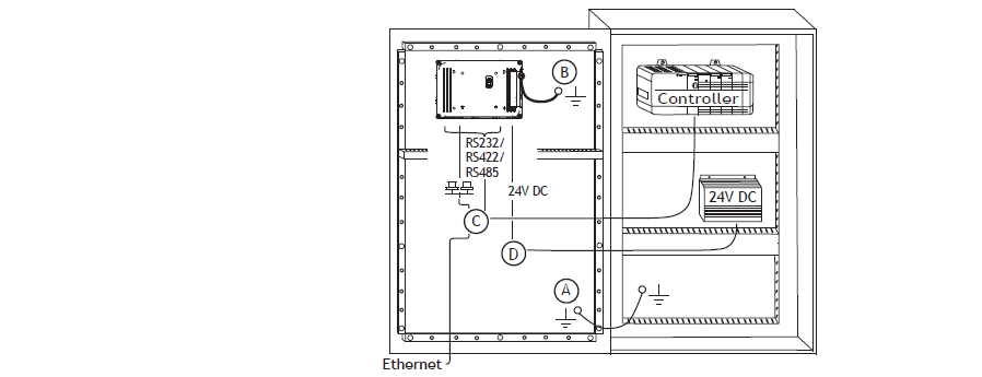
Question: How to ground the PP874 3BSE069271R1 operator panel?
Answer:
1. Connect a wire, that is sized correctly according to local electrical codes, between the quick-connect terminal connector on the operator panel and the chassis of the panel, see 2 in drawing above.
2. Connect a wire or grounding braid, that is sized correctly according to local electrical codes, between the chassis of the operator panel and the closest grounding point on the door, see 3 in drawing above.
3. Connect a strong but short grounding braid between the door and the device cabinet, see 4 in drawing above.
4. Twist the cables onto the 24 V DC feed, see 5 in drawing above. 2 turns around the ferrite core provide 4 times the suppression of 1 turn. 3 turns around the ferrite core provide 9 times the suppression of 1 turn.
Question: How to connect the cables?
Answer:
• The operator panel must be brought to ambient temperature before it is started up. If condensation forms, ensure that the operator panel is dry before connecting it to the power outlet.
• Ensure that the operator panel and the controller system have the same electrical grounding (reference voltage level), otherwise errors in communication may occur.
• Ensure that the voltage and polarity of the power source is correct.
• Separate high voltage cables from signal and supply cables.
• Shielded communication cables are recommended.

Common misspellings:
PP874 3SE069271R1
PP874 3BSE06927R1
PP784 3BSE069271R1
PP874 3BSE069217R1
PP874 3BSSE069271R1


