How to replace the backlight for the Allen Bradley PanelView Plus Terminals
- Share
- Issue Time
- May 25,2018
This section shows how to replace the backlight for the 700, 1000,1250, and 1500 terminals. The 1250 high-bright terminals do not havea replaceable backlight.
IMPORTANT Disposal: The backlights for these products contain mercury.Dispose of per applicable laws.
Follow these steps to replace the backlight.
- 1. Disconnect power from the terminal.
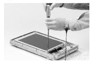
- 2. Remove the display module bezel.
IMPORTANT The 700 series C display is not secured by screws and is onlyretained by a bracket. Use care not to drop the display once thebezel is removed. - 3. Remove the four screws that secure the display bracket for the 700 series C display.
- 4. Remove the four screws that secure the LCD display for all other displays.
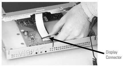
- 5. Lift the LCD display and detach the display connector from thecircuit board.The circuit board layout may vary for each terminal model.The location of the connector varies by model.
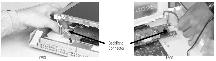
- 6. Detach the backlight connectors from the circuit board.The 1250 has one or two backlight connectors depending on theseries of the display. The 1500 has four backlight connectors.
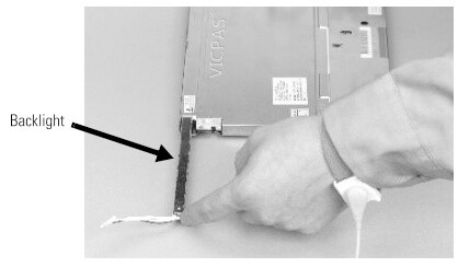
- 7. Follow these steps for the PanelView Plus 700 and 1000displays.
a. Press the retaining tab that secures the backlight and then pullout the backlight.
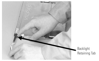
b. Insert the new backlight.
- 8. Follow these steps for the PanelView Plus 1250 and 1500displays.
a. Remove the screws that secure the backlights and remove thebacklights.
– The two backlights for the 1250 series A and B displays areeach secured with two screws. The single backlight for the1250 series C displays is secured with one screw.
– For the 1500 series B displays, remove the tape and thenremove the backlights.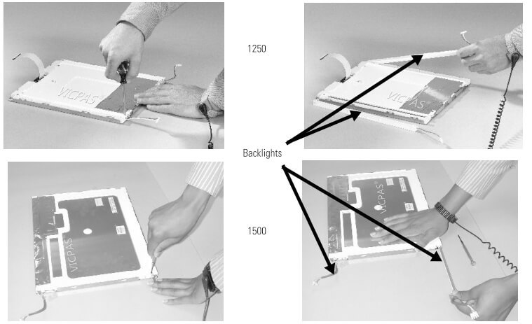
b. Insert the new backlights and then secure each with the samescrews from the previous step and torque to0.117 Nm (1.04 lb•in).
- 9. Attach the LCD display connector to the circuit board.Refer to step 5.
- 10. Attach the backlight connector to the circuit board.Refer to step 6.
- 11. Secure the LCD display.
a. Attach the display bracket then secure the display in thebracket for the 700 series C display.
b. Attach the four screws for all othe displays.
Tighten the screws and torque to 0.58 Nm (5…7 lb•in).
- 12. Replace the display module bezel.